
I recently attended a university course on embedded programming and needed to be able to debug AVR targets. I was given an MPLAB Snap debugger. I have in the past used OpenOCD with a fake STLink to debug STM32 targets, but OpenOCD does not seem to work with the Snap (please correct me if I am wrong).
The solution is Bloom. Bloom is an open source debug server for many different hardware debuggers and for many different targets. It works as a middle man between the hardware debugger and GDB and acts as a GDB server which you can attach your GDB to.
The target I am using is an Atmega2560, more specifically an Arduino Mega board. For debugging with the Snap we will connect to the Mega using JTAG. This interface is not enabled by default, so we first need to set the correct fuses on the Atmega chip to enable it.
To set the fuses the first time we need to do it through the ICSP header. Locate the ICSP header on the Arduino Mega board near the reset button as shown in this picture. If you have already enabled the fuse for JTAG debugging you can instead set the fuses through JTAG.

Connect the Snap to the ICSP header on the Arduino Mega according to the above pinouts.
Now we are ready to read out the current fuse settings so we can set them back in case we screw something up.
avrdude -p atmega2560 -c snap_isp -P /dev/ttyACM0 -U lfuse:r:-:i -U hfuse:r:-:i -U efuse:r:-:iYou will get output similar to this:
avrdude: AVR device initialized and ready to accept instructions
avrdude: device signature = 0x1e9801 (probably m2560)
avrdude: reading lfuse memory ...
avrdude: writing output file <stdout>
:010000006E91
:00000001FF
avrdude: reading hfuse memory ...
avrdude: writing output file <stdout>
:0100000010EF
:00000001FF
avrdude: reading efuse memory ...
avrdude: writing output file <stdout>
:01000000FD02
:00000001FF

avrdude done.  Thank you.
This can be a bit confusing to read, but in the above output the fuse values are 6E, 10 and FD. So the fuse values are in the second byte from the right in the top line in each output.
Now to calculate your new fuse values use the AVR fuse calculator. Select your AVR target from the dropdown list, in our case the Atmega2560.
Go to the bottom of the page where it says Current settings and type in the fuse values you read out from your board and click apply values.
Then scroll up to the previous section titled Manual fuse bits configuration and modify the settings as you like, but make sure that OCDEN and JTAGEN or turned on. It is also a good idea to turn on EESAVE to preserve EEPROM data when flashing.
Example of fuse values after enabling JTAG and setting other settings. After modifying the settings go down to Current settings again and read out the new fuse values.
Now it is time to flash the new fuse values to the Mega. Make sure to change the values in the below command with the ones you just calculated.
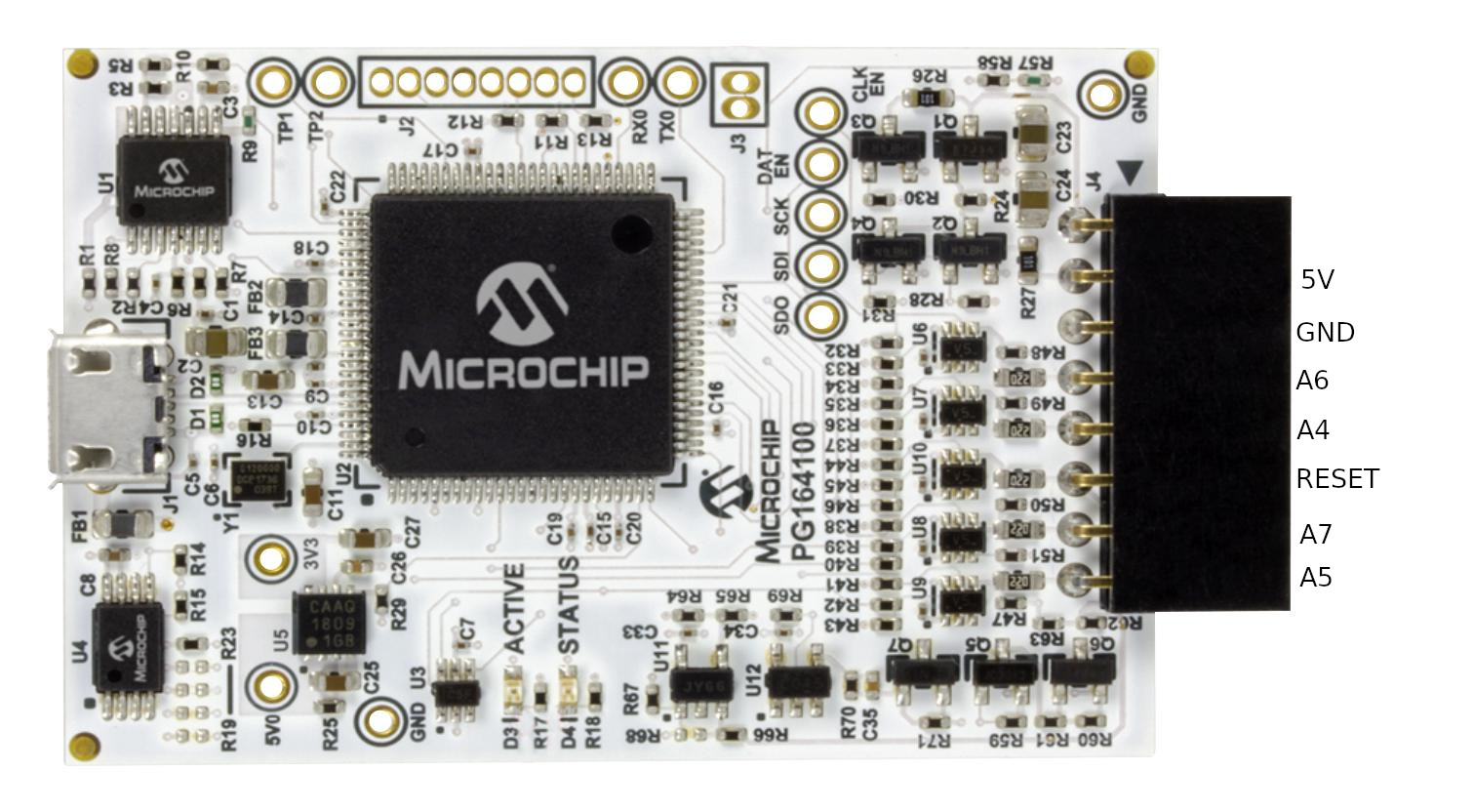
avrdude -p atmega2560 -c snap_isp -U lfuse:w:0xff:m -U hfuse:w:0x10:m -U efuse:w:0xfd:mAfter enabling the JTAG interface we can now connect the Snap debugger to the JTAG pins on the Mega, as shown in this image:
Bloom by default has a very annoying feature that makes for a slow experience. In the current version of Bloom every time you flash the target with a new firmware Bloom takes a snapshot of the entire EEPROM and then applies the backup after flashing the firmware.
This takes a very long time and there is currently no way to disable it. What I have done is build Bloom myself with the snapshot code commented out. Don’t worry, if you need persistent EEPROM you can still set the appropriate fuses to enable this in hardware.
First get a copy of the source code. Make sure to check out the develop branch, which contains some fixes to make it buildable with recent software versions.
Then we need to comment out the lines that backs up and restores the EEPROM data.
        //Logger::debug("Capturing EEPROM data, in preparation for chip erase");
        //auto eepromSnapshot = this->readMemory(
        //    TargetMemoryType::EEPROM,
        //    this->targetParameters.eepromStartAddress.value(),
        //    this->targetParameters.eepromSize.value()
        //);

        const auto responseFrame = this->edbgInterface->sendAvrCommandFrameAndWaitForResponseFrame(
            EraseMemory(Avr8EraseMemoryMode::CHIP)
        );

        if (responseFrame.id == Avr8ResponseId::FAILED) {
            throw Avr8CommandFailure("AVR8 erase memory command failed", responseFrame);
        }

        //Logger::debug("Restoring EEPROM data");
        //this->writeMemory(
        //    TargetMemoryType::EEPROM,
        //    this->targetParameters.eepromStartAddress.value(),
        //    std::move(eepromSnapshot)
        //);
src/DebugToolDrivers/Protocols/CMSIS-DAP/VendorSpecific/EDBG/AVR/EdbgAvr8Interface.cpp
Now building should be straight forward as long as you have all the reuirements. Refer to build and installation instructions in Bloom repo.
Create a bloom.yml file and configure it like so:
environments:
  default:
    debugTool:
      name: "snap"

    target:
      name: "atmega2560"
      physicalInterface: "jtag"

    debugServer:
      name: "avr-gdb-rsp"
      ipAddress: "127.0.0.1"
      port: 1442

insight:
  enabled: false
I had to disable insight to avoid Bloom from crashing because of a bug in some of the GUI code. I wish there was a way to build Bloom without a GUI, but unfortunately this is not possible at this time.
To start Bloom connect your debug tool and simply run bloom in the directory where your bloom.yaml is located.
Connect to Bloom from GDB:
(gdb) target extended-remote :1442Specify what binary to debug:
(gdb) file main.binFlash new binary to target:
(gdb) load